FAQ
Frequently Asked Questions
Question & Answer

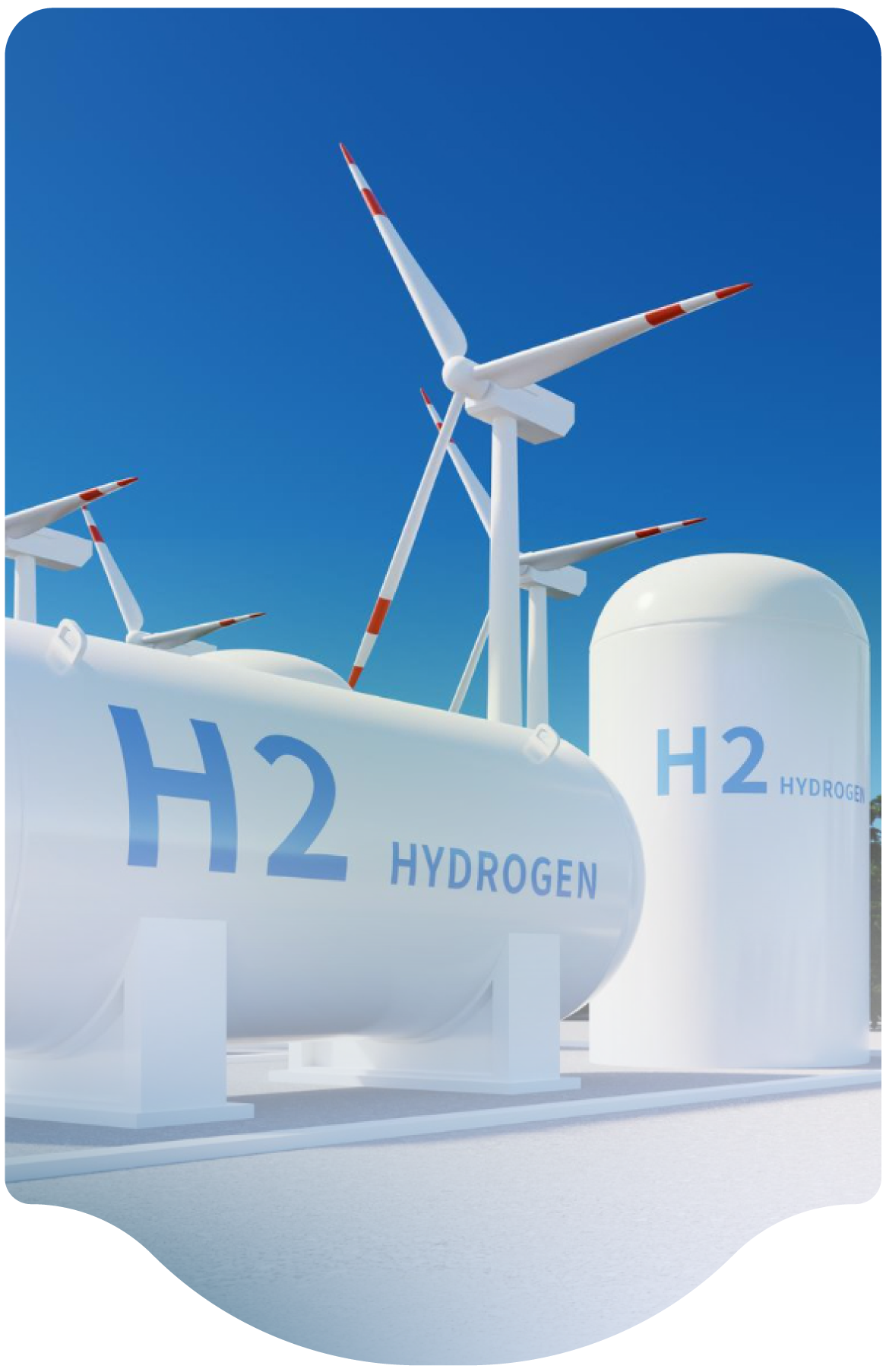
Relief device sizing for liquid hydrogen tanks follow recognized standards such as CGA S1.3. The sizing criteria include a worst-case scenario of an engulfing fire with loss of vacuum integrity.
LH2 tanks are unlikely to BLEVE due to the vacuum insulation outer jacket (usually carbon or stainless steel) preventing direct impingement of fire onto the main pressure vessel, as well as the…
There are several levels of documents which can be used to assist with the design, sizing, selection, and installation of the pressure relief device settings for LH2 tanks.
Pressure vessel design codes, such as the ASME Boiler and Pressure Vessel Code will provide minimum requirements for design of pressure vessels (including LH2 tanks), relief devices, and relief systems. However,…
Safety codes globally have a requirement to provide a positive means to isolate energy sources and hazardous substances prior to performing maintenance. For gaseous hydrogen systems, methods such as a blind flange, a double block valve arrangement or a double block and bleed valve arrangement can provide that positive isolation.
Installing a blind flange requires breaking the supply line…
Pressure relief systems may use reclosing devices like relief valves, non-reclosing devices like rupture discs, or a combination of both in parallel. Some systems may also be equipped with emergency blowdown systems that are operated by control systems. Selection of the proper devices is dependent on the system design and relative hazards. Variables that affect the selection include the type…
API 520, Sizing, Selection, and Installation of Pressure-relieving Devices Part I - Sizing and Selection, was written for use in the process industries in gas and liquid service.
CGA S1.3, Pressure Relief Device Standards-Part 3-Stationary Storage Containers for Compressed Gases was written for fixed equipment in gas service.
Which standard to use depends on the choice by the owner…
Equation 6.3.1.1 in CGA S1.3 is based on modeling to API methods described in: Heitner, T. Trautmauis, and M. Morrissey, “Relieving Requirements for Gas Filled Vessels Exposed to Fire,” 1983 Proceedings-Refining Department, Volume 62, American Petroleum Institute, Washington, D.C., pp. 112-122.
This method considers the transient nature of the vessel warming in combination with the…
Many methods are used to mitigate the risk of a tube trailer hose loss of containment incident. Examples that otherwise exceed code requirements are provided below. These have been deployed in various combinations depending on the risk analysis for a particular system:
A "drop and swap" delivery system using tube trailers is a common and accepted method of supply for both industrial and fueling station applications. While NFPA 2 - 2023, paragraph 10.6.3.5 states, "The use of hose in a hydrogen dispensing system shall be limited to vehicle fueling hose," this is intended for the dispenser itself, not the entire fueling station. This does not limit the use of…
Gaseous hydrogen can be stored forever as long as the system integrity is maintained. However, liquid hydrogen is “use it or lose it” and will boil from system heat leak and build pressure unless it is used or vented. This is not usually an issue for continuous use or low-pressure applications which can use hydrogen gas pressure directly from the tank.
For intermittent or high…
An annual inspection of safety devices is recommended. Testing requirements will be based on the type of device and a quantified risk analysis. Typical replacement or function testing of relief valves is between 5 and 10 years depending on the application within the industrial gas industry. Rupture discs are not tested but are frequently replaced on an interval based on manufacturer…
We are the leaders in the building industries and factories. We're word wide. We never give up on the challenges.